
Introduction and application:
Building electrical, telecommunication and recently informatics networks outside walls has been a widely adopted practice for decades. The most important advantages of cable trunking are the easy accessibility, modification and extension. Flats and public buildings need a safe and elegant, aesthetical design and the recent construction technology, materials make possible to meet these requirements. Isonal 2000® system complies with the requirement of the unitary European technical prescriptions – MSZ EN 50085 – what will be valid from 2004.
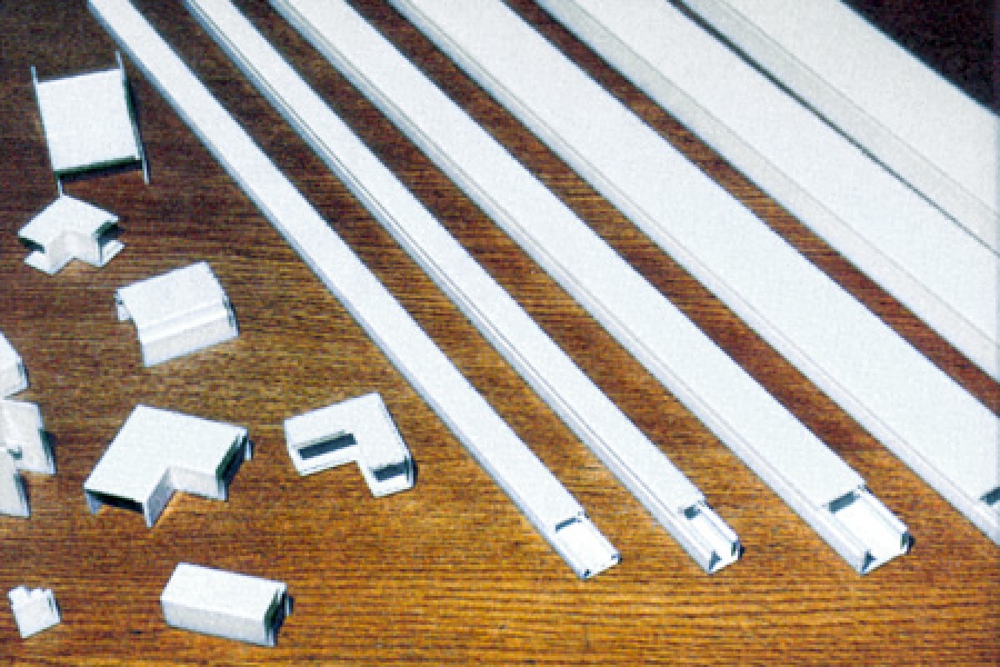
The following accessories of ISONAL 2000® cable trunking system give a good construction possibility to the MSZ EN 50085 type of CTS system, which is with opening cover and can be assembled on the wall or the ceiling.
Quality assurances:
Certificate of type testing: MEEI D1280 K 109 / CCA/HU 0088
Production: MSZ EN ISO 9001:2000 Certificate: 08/100/9517/6
Size and collection of profiles:
|
Nominated size of trunking (width x height) (mm) |
||||||
|
Description of profiles |
18×9 |
16×16 |
25×16 |
40×16 |
40×25 |
50×25 |
|
Internal bend |
X |
X |
X |
X |
||
|
External bend |
X |
X |
X |
X |
||
|
Flat bend |
X |
X |
X |
X |
||
|
Equal T unit (same size) |
X |
X |
X |
X |
||
|
End Cap |
X |
X |
X |
X |
||
|
Equal ceiling T unit |
25/16 |
25/25 |
||||
|
Unequal T unit (different size)) |
25/16 |
|||||
|
Coupler (cover) |
X |
X |
||||
|
Coupler |
X |
X |
||||
Trunking collection:
|
Code |
||||||
|
Execution ( L ) |
||||||
|
2m |
3m |
|||||
|
|
Nominated size |
A |
B |
Standard |
Self Adhesive |
Standard |
|
18×9 |
18 |
9 |
X |
X |
X |
|
|
16×16 |
16 |
16 |
X |
X |
X |
|
|
15×18 |
15 |
18 |
X |
|||
|
25×16 |
25 |
16 |
X |
X |
X |
|
|
25×25 |
25 |
25 |
X |
|||
|
32×50 |
32 |
50 |
X |
|||
|
40×16 |
40 |
16 |
X |
X |
||
|
40×25 |
40 |
25 |
X |
X |
||
|
50×25 |
50 |
25 |
X |
X |
||
|
50×50 |
50 |
50 |
X |
|||
|
50×100 |
50 |
100 |
X |
|||

Remark: Standard execution can be made with holes on the bottom (Code: L)
Internal Bend:
|
Nominated size |
A |
B |
C |
D |
E |
Code |
|
16×16 |
15,8 |
15,8 |
19,4 |
34 |
10 |
A1 |
|
25×16 |
25,1 |
15,8 |
28,7 |
41 |
19 |
A2 |
|
40×16 |
40,1 |
15,8 |
43,7 |
48 |
17 |
A3 |
|
40×25 |
40,1 |
24,8 |
43,7 |
57 |
17 |
A4 |
External bend
|
Nominated size |
A |
B |
C |
D |
E |
F |
G |
Code |
|
16×16 |
15,8 |
15,8 |
19,4 |
42,5 |
10 |
24,9 |
17,6 |
EA1 |
|
25×16 |
25,1 |
15,8 |
28,7 |
42,5 |
15 |
24,9 |
17,6 |
EA2 |
|
40×16 |
40,1 |
15,8 |
43,7 |
59 |
15 |
32,4 |
17,6 |
EA3 |
|
40×25 |
40,1 |
24,8 |
43,7 |
59 |
15 |
32,4 |
26,6 |
EA4 |
End cap:
|
Nominated size |
A |
B |
C |
D |
E |
F |
Code |
|
25×16 |
13,5 |
25 |
22 |
13 |
16 |
13 |
SE2 |
|
40×16 |
28,5 |
40 |
37 |
13 |
16 |
13 |
SE3 |
|
40×25 |
28,5 |
40 |
37 |
22 |
25 |
13 |
SE4 |
|
Nominated size |
A |
B |
C |
D |
Code |
|
16×16 |
16 |
16 |
13 |
13,4 |
SE1 |
Coupler:
|
|
|||||
|
Nominated size |
A |
B |
C |
D |
Code |
|
16×16 |
16 |
16 |
13 |
13,4 |
SE1 |


Coupler (cover)
|
|
||||||
|
Nominated size |
A |
B |
C |
D |
E |
Code |
|
16×16 |
15,8 |
17,6 |
19,4 |
46 |
12 |
C1 |
|
25×16 |
25,1 |
17,6 |
28,7 |
50 |
12 |
C2 |


Properties and applicable fields:
Structure elements, network construction:
With the most often applicable 6 trunking sizes and 30 profiles of the MSZ EN 50085 type of CTS system you can establish a network according to requirements.
This system makes possible a cabling and route at your discretion on the wall and ceiling equally.
It is easy to extend an existing network, or to establish embranchments and extensional or plane reversing with the profiles. For the bigger sizes of cable trunking a cable fixing is applicable.
Mechanical properties:
The perfect connection between the well designed bottom and cover and strengthened catches of the profiles make possible an easy assembling and tight fit. The cover from the bottom can be removed only with a tool. The cable trunking system does not include any thinned and broken out parts, it means it has no “vulnerable points”.
Impact resistance is 2 J, what means a safe protection in average mechanical stress.
Electric properties:
The material of all elements of this cable trunking system is the well known rigid PVC with perfect electrical insulation, it has a perfect shock-proof in the compact statement. The system has no part, which could be on voltage at the application, so it does not need be earthed, but it cannot be used as an earthing.
Thermal properties:
The cable trunking system is safely applicable between a temperature of – 5 °C and + 60
The cable trunking elements against flame are typical for PVC, i.e. they do not spread the flame and after removing the ignition flame they will be extinguished. The material of the cable trunking system should be protected from sudden heat load and from permanently radiant heat.
Protection from external impacts:
Protection from external impacts:
Between the cable trunking elements will not be installed any stuffing-box or stuffing to protect the elements from dust, humidity and corrosion impact. The cable trunking cover and the elements are joining together with overlapping, but do not protect from dust (graininess is smaller than 1 mm), water and corrosion impact.
This cable trunking system makes a protection of IP 40
Electromagnetic compatibility:
If the cable trunking system works functionally, the electromagnetic compatibility is passive.
Selection of cable trunking:
| Nominated size of cable trunking (mm) | Calculated efficient cross-section (mm2) | Applicable cross-section by 0,6 filling (mm2) | Capacity (NYM 3×1,5mm2 diameter 10,5) db (x) |
| 18×9 | 75 | 45 | |
| 16×16 | 140 | 84 | 1 |
| 18×15 | 183 | 110 | 1 |
| 25×16 | 220 | 132 | 2 |
| 25×25 | 426 | 256 | 3 |
| 40×16 | 410 | 246 | 3 |
| 40×25 | 720 | 432 | 5 |
| 50×25 | 860 | 516 | 6 |
| 50×32 | 1200 | 720 | 6 |
| 50×50 | 2064 | 1238 | 9 |
| 50×100 | 4214 | 2528 | 22 |
Principle of selection:
The total amount of cable cross-section should be less or equal to the applicable cross-section of cable trunking.
Fixing of cable trunking:
With screwing: application with button-head screw, washer and chock.
Size and number of screws:
| Size of cable trunking | Size of screw | Number of screw as metres |
| 18×9, 16×16 | Diameter: 3×30 | min. 3×1 pc |
| 25×16 | Diameter: 4×40 | min. 3×1 pc |
| 25×25 | Diameter: 4×40 | Min. 3×1 pc |
| 40×16, 40×25 | Diameter: 4×40 | min. 3×2 pc |
| 50×25, 50×32, 50×50, 50×100 | Diameter: 4×40 | min. 3×2 pc |
Fixing set up:
| Size of cable trunking | Type of arrangement |
| 18×9, 16×16, 25×16 | In a single-row in the middle line of the cable trunking |
| 40×16, 40×25, 50×25 50×32, 50×50, 50×100 | In double rank settled symmetrical to the middle line of the cable trunking, spacing 20mm |
Setting up fixing places at 100 mm from the joining of the cable trunking bottoms and profiles are suggested.
Attention: Only insulated fixing elements are applicable for the walls (supporter) made of conductive material.
Double sided self adhesive tape: Quick fixing for sizes at 18×9, 16×16 and 25×16
Remark: This mode is proposed for solid, dustless, non-scaling walls.
Suggestions for fixing:
- Examination of application mode for cable trunking at the given place according to the written properties and applicable circumstances.
- Examination of the determinant factors for cable trunking route: construction of the building and walls, location of built-in furniture and networks.
- Appointing of the route and embranchments of the cable trunking.
- Measuring of the lineal parts of the cable trunking.
- Appointing those places where fixing is not applicable: for example water or other built-in cable networks.
- Appointing the fixing places for the trunking bottom.
- Selection of trunking according to the planned cable sizes. (suggested chapter: Selection of cable trunking)
- Definition of profiles for joining, embranchments, reversing according to the table of cable trunking size and profile collection.
- Dimension of the trunking bottom
Cutting mode for plastic profile:
– with hands: fine teethed saw, for example: metal saw
-with machine: circular saw: diameter: 250 mm, with 80-108 saw-teeth. Suggested cutting speed: 0.4 – 0.5 m/min for 2800 rotation/min. . - Preparing the fixing holes on the bottom of the cable trunking according to chapter of Cable trunking fixing.
- Appointing the fixing holes on the wall (remarking or measuring)
- Preparing the fixing holes on the walls and screwing up the bottom of the cable trunking.
- Dimension of the cover in accordance of the catches of profiles
- Cabling
- Putting together the cover and profiles.
Most important material properties:
Type of material: rigid PVC ( VSZM AS – 04 / 96 ) including stabilizer and sliding and shockproof addition
Application field: Inside of buildings, protection from medium mechanical impact, for extruded and injection moulded profiles
Colour: RAL 9001 – cream white, RAL 9010 – clear white
Mechanical properties:
| Tensile strength: | min. 38 N/ mm2 | VSZM – V 001/1996 |
| Elongation at break: | min. 25 % | VSZM – V 001/1996 |
| Impact-bending strength: | MSZ 7751 | |
| Charpy feathered: | 23 °C :min. 10 KJ /m2 | |
| 0 °C :min. 6 KJ /m2 |
Thermal properties:
- Ignitability: hardly inflammable according to VO UL 94
- it does not spread the flame, after removing the ignition flame it will be extinguished.
- Vicat softening point MSZ ISO 306 (at 5 kg weight) min 80 °C
- Linear expansion factor : ~ 7 x 10⁻⁶ 1/°C
(it means 1,4 mm modification in length at 20 °C temperature modification) - Examination with heater filament 960 °C. MSZ IEC 695
Electrical properties:
- Spark-resistance: min. 20 KV /mm
- Surface resistance : min. 1012 ohm
- Specific volume resistance : min. 1015 ohm/cm
- Relative dielectric constant : ~ 2,7
Resistance to chemicals: (+) good resistance (o) average resistance (-) no resistance
| Acetone | – | Linseed oil | + |
| Drinks with alcohol | + | Nitrobenzene | – |
| Ammonia | + | Vegetable oil | + |
| Mineral oil | – | Rock-tar | + |
| Petrol | – | Hydrochloric acid ( 30% ) | + |
| Citric acid | + | Salting liquid | + |
| Glycerine | + | Soup solution | + |
| Iodine | – | Milk | + |
| Sulphuric acid ( 50% ) | + | Turpentine | + |
| Sulphuric acid ( 80% ) | – | Water | + |
For materials not listed here, please ask for the manufacturer reference.
Types of cable trunking (according to the information of MSZ EN 50085):
Types of CTS for construction to walls and ceiling.
| Marked numbers on the picture | Types | Content | Construction |
| 1,7,11,12,13 | CTS | Insulated conductors, wires and cables | Onto the surface of wall and ceiling, constructed on the wall horizontal or vertical, hung up to the ceiling |
| 5 | CTS | Insulated conductors, wires and cables, and instruments (switch, connector, breaker, etc.) | Onto the surface of wall and ceiling, constructed on the wall horizontal or vertical |
| 3,9 | CTS | Insulated conductors, wires and cables | Into the surface of wall and ceiling, recessed in the wall horizontal or vertical |
| Not marked | CTS | Insulated conductors, wires and cables, and instruments (switch, connector, breaker, etc.) | Into the surface of wall and ceiling, recessed in the wall horizontal or vertical |
| 6,15 | Floor border CTS | Insulated conductors, wires and cables | Onto the surface of wall |
| Not marked | Floor border CTS | Insulated conductors, wires and cables, and instruments (switch, connector, breaker, etc.) | Onto the surface of wall |